
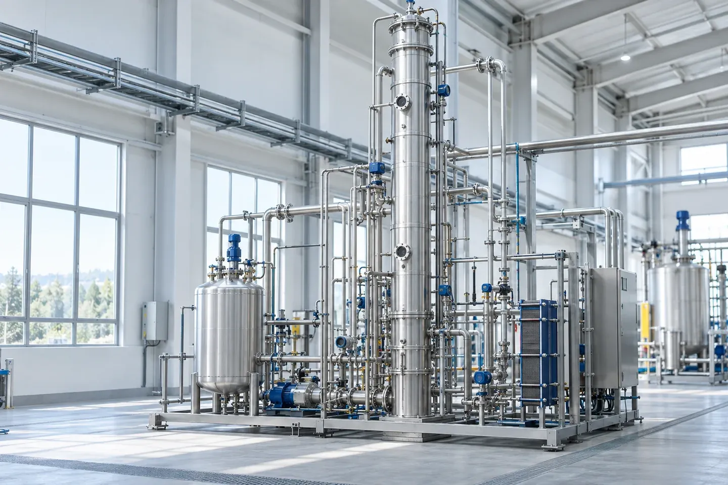
PC circulates between absorption and regeneration
Propylene carbonate (PC) can serve as a physical CO₂ absorbent in appropriately designed processes. Fluor’s published Fluor Solvent process uses PC to contact CO₂-containing gas with liquid, transferring some CO₂ from the gas into the liquid phase. The rich solvent then enters regeneration, releasing gas to produce a lower-loading lean solvent that returns to absorption.
Rich and lean describe gas loadings of the same circulating liquid at two locations, not two different raw materials. Regenerated solvent may still contain some CO₂, so the difference between loadings before and after absorption matters. Each cycle does not begin with completely gas-free PC. Fresh material is only one part of the plant’s material inventory; the circulating state connects continuous operation.
Physical absorption relies on gas dissolution in a liquid and changes in equilibrium. It differs from amine processes that rely mainly on reversible chemical reactions. Both require absorption and regeneration equipment, but their driving forces, circulating compositions and regeneration arrangements differ. Replacing an equal volume of amine solution with PC does not create an equivalent process.
Technical references: [1]
Consider CO₂ partial pressure before total pressure
Under the ideal-gas approximation, CO₂ partial pressure can be written as p_CO₂=y_CO₂×P_total, where y_CO₂ is the mole fraction in the same gas phase and P_total must be absolute pressure. If gas volume fraction approximates mole fraction, the state and dry or wet basis must also be consistent. High total pressure does not necessarily mean high target-gas partial pressure; composition also determines the result.
Consider a hypothetical example used only for explanation. Gas source A has a total absolute pressure of 40 bar and a CO₂ mole fraction of 1%, giving an approximate partial pressure of 0.4 bar. Gas source B has a total absolute pressure of 10 bar and a CO₂ mole fraction of 10%, giving approximately 1 bar. B has lower total pressure but higher CO₂ partial pressure. These numbers are not recommended operating conditions and do not establish that B is necessarily more economical in a complete plant.
If composition is reported on a dry-gas basis but pressure refers to a water-containing gas, multiplying them directly may mix bases. High-pressure conditions may also require fugacity or another treatment of non-ideality. This multiplication is therefore useful for introducing partial pressure, but cannot replace an actual vapor–liquid equilibrium model or process design.
Partial pressure is not the only condition. The liquid’s existing CO₂ loading, the gas–liquid contact location and temperature influence the mass-transfer driving force between phases. Gas composition and liquid loading change along the absorber. Inlet total pressure alone cannot establish whether the outlet meets its target.
Technical references: [2]
How conditions affect different parts of the cycle
Material balances explain working capacity; mass transfer, equipment and energy use determine the feasibility of the actual cycle.
Gas must be released before absorption can be repeated
Fluor’s process description includes staged pressure reduction and regeneration arrangements such as vacuum or stripping. Lower pressure releases some dissolved gas, and the lean solvent returns to absorption. Gas from different stages may require recovery or further treatment. These are arrangements in that published process, not an equipment combination required for every PC plant.
Temperature also creates trade-offs. Fluor’s documentation explains that lower absorption temperatures increase CO₂ capacity in its process, affecting the required solvent circulation. However, cooling may increase refrigeration demand and alter flow and mass transfer. Greater capacity at the absorber does not automatically mean lower total system energy consumption.
Deeper regeneration can reduce lean-solvent loading, creating more capacity for the next absorption cycle. At the same time, vacuum, stripping or gas recovery may increase the load. The design objective is not to pursue the richest possible rich solvent or the leanest possible lean solvent in isolation, but to establish a sustainable cycle for the feed gas, purification target and equipment conditions.
Technical references: [2]
What cyclic working capacity adds to a single solubility value
On a consistent measurement basis, cyclic working capacity equals rich-solvent loading minus lean-solvent loading after regeneration. For example, subtraction is directly meaningful if both use mol CO₂/kg solvent. A value per kilogram of rich liquid cannot be mixed with one per kilogram of pure solvent. Working capacity describes how much target gas a unit of circulating solvent actually removes each cycle.
Suppose cycle A has rich and lean loadings of 2.0 and 1.5 mol/kg solvent, giving a working capacity of 0.5 mol/kg. Cycle B has respective loadings of 1.6 and 0.8 mol/kg, giving 0.8 mol/kg. B has a lower rich loading but a larger loading difference. These teaching values are not measured PC data and do not mean that B necessarily has lower energy consumption or cost.
In a simplified material balance that neglects losses and other changes, solvent circulation multiplied by the loading difference explains the quantity of CO₂ carried over a given time. Real equipment is also limited by mass-transfer rates, contact area, gas–liquid distribution and residence behavior. Adequate equilibrium capacity does not mean that finite-sized equipment actually reaches equilibrium. Working capacity is important for understanding circulation, but cannot replace equipment calculations.
Technical references: [2]
Co-absorption, water and energy-accounting boundaries
Other components matter when PC absorbs the target gas. Fluor’s documentation links relatively low light-hydrocarbon solubility with flash-gas recovery, showing that co-absorption losses belong in process assessment. Relatively low does not mean zero. If released gas contains valuable feed components, their recovery and destination affect material utilization and downstream compression load.
The process documentation also states that the solvent can absorb water from the feed gas. Water in a circulation loop is therefore more than a fresh-material test value; it can enter continuously with the gas. Incoming, outgoing and makeup streams jointly influence circulating-liquid composition. Battery-solvent low-water targets cannot be applied mechanically to infer that every gas-treatment system needs the same limit.
Fluor’s statement that external regeneration heating is unnecessary does not mean zero energy consumption. Circulation pumps, refrigeration, vacuum, gas recovery and subsequent compression may all consume energy. Comparisons must specify whether the boundary covers only regeneration or the entire capture and treatment system. Omitting one heat-input item cannot establish zero total energy consumption.
Fresh material and circulating liquid must also be distinguished. Fresh-material specifications describe the initial charge or makeup material; circulating liquid is additionally affected by feed contaminants, equipment contact and operating history. Changes in purification performance need to be considered together with feed composition, temperature, pressure, circulation rate and regeneration state. Raw material names or makeup quantities alone cannot establish the cause. Low vapor pressure does not mean no losses or no need for personnel protection under every operating condition.
Connecting raw material specifications with plant performance
Lixing supplies PC raw material, with supply discussed against specifications accepted by the plant designer. Absorbent selection, process licensing, equipment capability and purification targets are determined for each project. Conforming raw material addresses the input; an appropriate absorption and release cycle enables sustained use of that material with the given feed gas.
Raw material enquiries
- Makeup for an existing plant or use in a new project
- Approved PC raw material specification, if any
- Quantity, packaging and delivery location, if established
Common questions
Can a pressure-gauge reading be used in the partial-pressure formula?
The teaching formula uses absolute pressure. Gauge and absolute pressure have different reference bases, and composition must use a consistent dry or wet basis. High-pressure design must account for non-ideality.
Can PC directly replace an existing amine solution?
A simple equal-quantity substitution is not appropriate. Physical and chemical absorption have different driving forces and regeneration arrangements. The process designer needs to assess the process and equipment.
Technical references
- [1] Fluor Solvent Process
- [2] Fluor: Fluor Solvent section in The U.S. Carbon Capture and Storage Market
These sources provide further explanations of application principles. Delivery requirements for Lixing raw materials are defined by the product specification agreed by both parties.